Soldering Tips & Working life
How to also achieve optimum results with lead-free
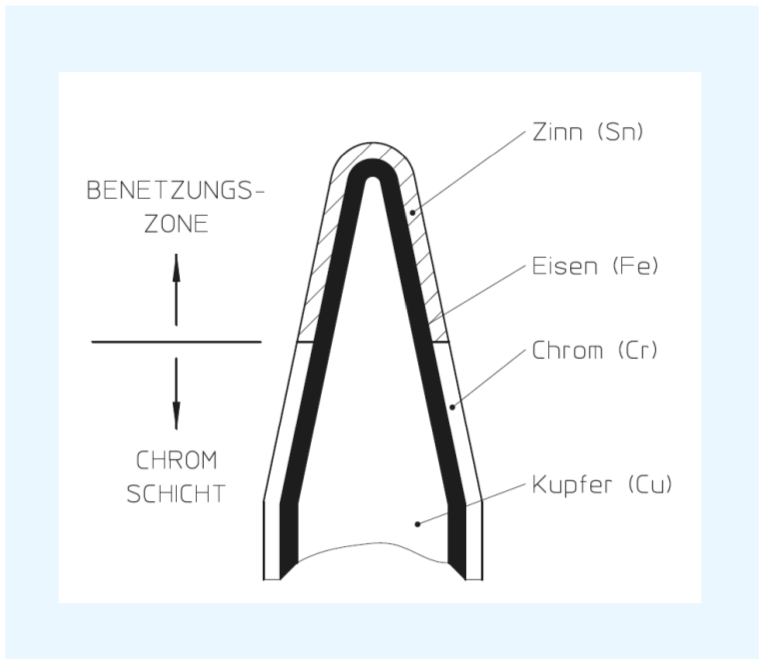
Build-up of the soldering tip
Copper core:
Tellurium copper, material with reduced oxidisation, easily cut. Responsible for the thermal conductivity of the soldering tip.
Iron layer:
Is applied galvanically. Responsible for the life expectancy of the soldering tip. Alloy deposit rate 40 – 50 solder cycles per μm of iron.
Chromium layer:
Is applied galvanically. Non-wettable part of the soldering tip. Responsible for the limit of the wettable zone.
Wettable zone:
(see chrome-free zone) Responsible for the solderability of the soldering tip.
Lead-free Pre-tinning:
Responsible for activation of the soldering tip and the ability for wetting in the delivered condition.
Pre-tinning can be applied galvanically as well as through immersion tin-plating.
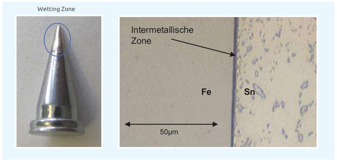
The occupation zone of the soldering tip
 The wetting zone contributes to heat transfer.
The intermetallic connections are a prerequisite for a wetting zone between the iron layer (Fe) and the tin part (Sn) of the solder alloy.
At the appearance of an intermetallic connection one can assume that the soldering tip has formed a solid connection with the solder alloy and is wettable.
The number of the intermetallic connections increases with temperature and leads to a higher rate of corrosion through the solder fl ux, a higher rate of separation and increased oxidation.
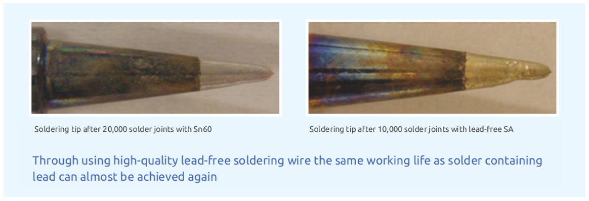
Wear and tear on the soldering tip
The copper core of the soldering tip is coated with a layer of iron for protection against corrosion by the soldering fl ux and migration by the soldering alloy.
With a tin content of over 95% in lead-free solder the separation (migration) of the iron layer presents a new additional problem for the working life of the soldering tips.
The corrosion rate and the rate of separation and therefore the erosion to the soldering tip are dependent on the alloy and temperature.
Mechanical infl uences through customer-specifi c applications additionally contribute to wear and tear.
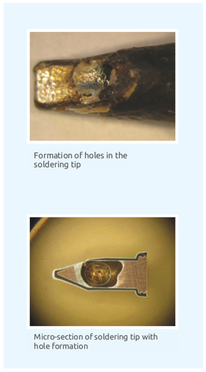
Sooner or later every soldering tip will be worn down through the soldering process. i.e. the iron layer has been used up and no longer off ers any protection for the copper core which is quick to corrode.
In this way the working life of the soldering tip is determined by the thickness of the iron coating.
With an iron layer that has worn down the soldering tip has reached the end of its working life. This condition can be recognised by the formation of holes in the copper core.
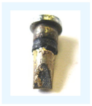
The wear and tear on the soldering tip can be divided into 3 areas in the following manner:
- Chemical reaction (corrosion)
- Metallic reaction (separation)
- Mechanical load
The soldering tip is a wear and tear part. The working life of the soldering tip can be increased considerably through correct attention to the soldering temperature and the correct choice of soldering wire.
Oxidation of the Soldering Tip
The soldering tip oxidises in an atmosphere containing oxygen and forms a layer of oxide on the top surface.
This oxide layer can usually no longer be penetrated by the soldering flux and remains non-wettable.
Non-wettable soldering tips off er signifi cantly reduced thermal transfer.
The risk of oxidation increases with rising temperature (450°C < 1min).
A soldering tip wetted with soldering tin prevents the introduction of oxygen to the wetted surface and prevents oxidation.
The oxidation risk can be considerably reduced with appropriate care of the soldering tip. (Temperature, cleaning, standby function, tip activator).
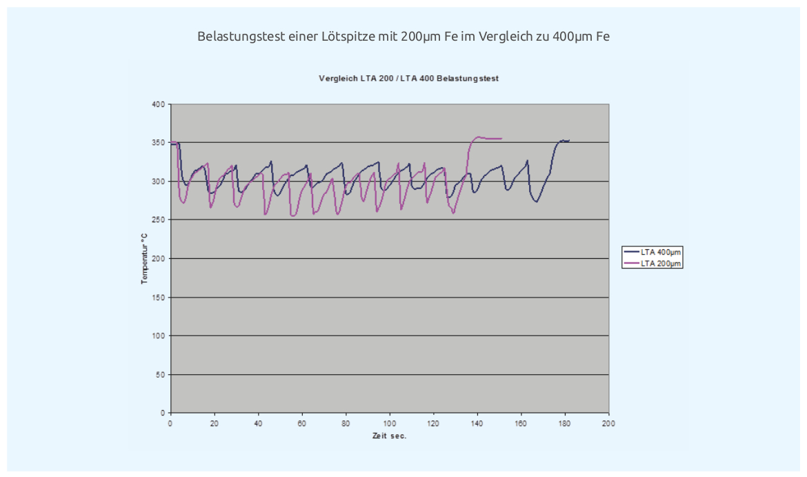
The iron layer on the soldering tip
The iron layer is applied galvanically to the copper core and the layer thickness is 150 μm to 400 μm, depending on the geometry of the soldering tip.
The galvanic treatment of the soldering tip presents a very intense technical process during the manufacture of the soldering tip.
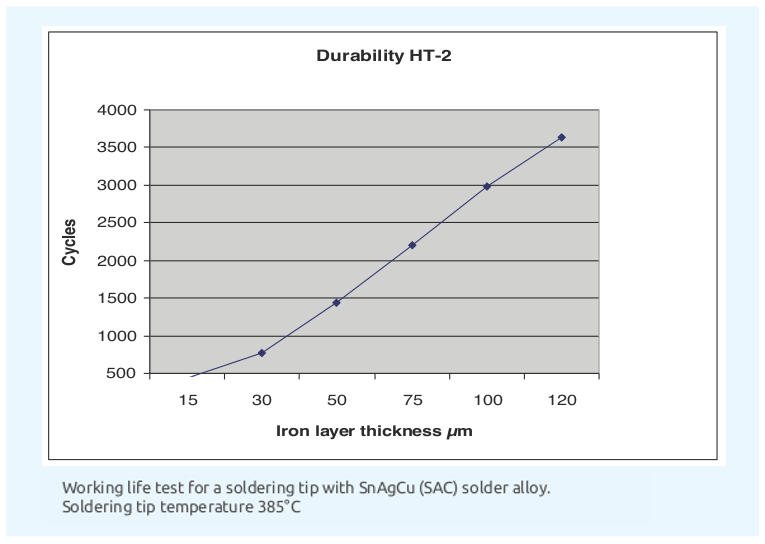
A linear relationship exists between the thickness of the iron layer and working life of the soldering tip.
The iron layer has three essential properties.
- Protection against wear and tear
- It is easily wettable
- Spec. thermal conductivity 5 times worse than cooper. (disadvantage)
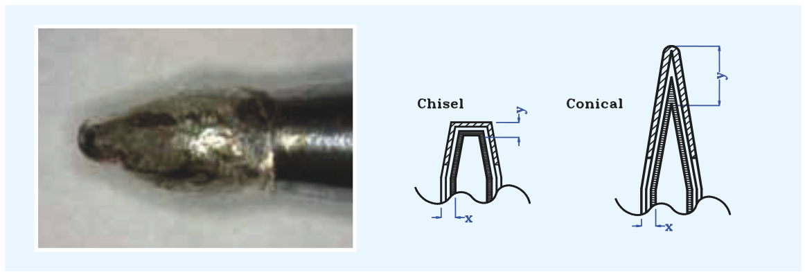
Influence of the Iron Layer on Soldering Tip Geometry
The thickness of the iron layer is adjusted according to the geometry of the soldering tip.
A thick iron layer reduces the thermal conductivity and has a particular eff ect on fine, conical soldering tips.
Conical soldering tips due have a lower copper mass at the front end to their geometry, in addition within the wetting zone the iron layer increasingly forms a pure iron tip.
For this reason the maximum thickness of an iron layer for fi ne soldering tips is limited by physics and is < 150 μm. Larger iron layers restrict the effi ciency of the soldering tip to too high a degree.
When soldering with fi ne tips, the eff ect of drops of solder distributing themselves on the wetting surface upwards / to the back occurs. This eff ect is minimised with an appropriate thickness of iron layer.
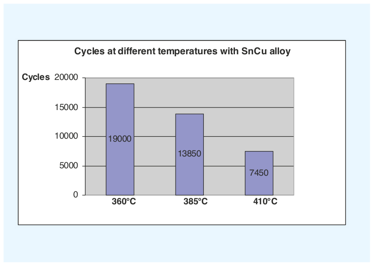
The influence of temperature on the working life of the soldering tip
The temperature of the soldering tip has a signifi cant infl uence on the working life of the soldering tip.
The corrosion rate and the separation rate increase very strongly with increases in temperature. The wear and tear increases over-proportionately.
With an SC alloy the working life in the temperature region between 360°C and 410°C on average reduces by 230 Solder joints / °C (40%)
Influence of the Iron Layer on Performance
With an increase in thickness of the iron layer we achieve a reduction in the thermal transfer behaviour at the same time. With an attempt to compensate this by increasing temperature the situation would be signifi cantly worsened.
Increases in temperature increase the separation of the soldering tip with the additional risk of oxidation making the soldering tip non-wettable.
Reduced temperatures (we recommend 350°C - 385°C) and good thermal transfer are fundamental prerequisites when working with lead-free solder. This means, the use of the largest possible shape of soldering tip and the use of a chisel shape tip instead of a conical shape are preferable.
The soldering equipment used is equally an important component when soldering with lead-free solder. Losses in thermal conductivity behaviour through an increased iron layer can be compensated using the more effi cient „silver line“ soldering tool.
The patented „silver line“ soldering tool from Weller fulfi ls these requirements through an optimum control mode, being quick to heat up and the best possible thermal transfer .
Directions for soldering, to achieve optimum results even with lead-free solder
Avoid increases in temperature or solder temperatures above 385°C. The wear and tear on the soldering tip increases drastically, the solder flux burns too quickly and causes solder flux residues on the soldering tip. A lower solder temperature reduces the risk of oxidisation and reduces solder flux splashes. „
Temperature increases can be prevented by using efficient „silver line“ soldering tools from Weller, with optimum thermal transfer characteristics.
Use of the largest possible soldering tip dimensions in order to optimise the heat transfer.
Use of dry cleaning helps better keep the soldering tip wettable.
Clean the soldering tip before the soldering process and not after it. Avoid dry, cleaned soldering tips in the soldering iron rest stand when the soldering tool is not in use.
Use functions to reduce the temperature (standby, auto off, switch at rest) or switch your soldering tool off during longer breaks in soldering.
Regular tin plating of the entire wetting zone and/or the use of a tip activator keeps the wetting of the soldering tip in good order.
The working life of the soldering tip can be increased through using micro- alloyed solders.
Dr. Fischer
Development Manager Weller GmbH